Siemens Rail Installation

NOTICE: General Reference Only
The information provided in this Knowledge Base is for general reference purposes only and does not constitute project-specific guidance. SLD Technology products are engineered to order, and their installation must comply with all applicable codes, standards, and project-specific specifications. In all cases, the approved project documentation and requirements take precedence over any general information contained herein. For project-specific instructions, contact your SLD Project Manager or email support@sldus.com.

WARNING: Failure to Follow Safety Precautions May Result in Serious Injury or Death
All installation and maintenance activities must comply with applicable OSHA, ANSI, and local safety regulations. Only qualified personnel should perform work on or around AirFRAME systems. Follow all instructions in the product installation manual, and adhere to proper lockout/tagout procedures, personal protective equipment (PPE) requirements, lifting safety, and environmental controls. Improper handling or installation may result in electrical shock, falls, equipment damage, or hazardous exposures. Refer to project-specific safety plans and site protocols. For questions or clarification, contact your SLD Project Manager or the SLD Support Team at: support@sldus.com before proceeding.
Introduction
SLD Technology’s AirFRAME® ceiling system supports a variety of ceiling-hung imaging equipment. These imaging systems, along with other ceiling-mounted equipment supported by AirFRAME, are attached to the structure above using bolt-on deep-channel Unistrut (P5500T) assemblies manufactured by SLD.
Due to the HSS tube steel frame construction of AirFRAME, Unistrut is provided only at the locations necessary to support the equipment rails. This eliminates the structural need to span Unistrut across the entire ceiling, helping maintain structural strength while allowing for superior airflow into the surgical space.
Siemens ceiling-hung imaging equipment installations require temporary chain hoist connection points to facilitate raising the C-arm into position during installation. These hoist points are needed only during installation and removal of the C-arm itself. Rather than extending Unistrut solely to accommodate these temporary rigging points and unnecessarily impacting airflow, SLD provides coordinated support locations for them.
Figure 1: Raising the ceiling stand
Support for these temporary anchor points may be provided at existing planned support locations or by adding support within another area of the AirFRAME system. Depending on the installation, this support may consist of either a bracket mounted to the tube steel structure or SLD’s removable Rail Install Tool.
Coordination Requirements
The required temporary hoist support locations must be identified during design and coordination so that the necessary structural support can be incorporated into the AirFRAME system.
These support points may be located:
- At existing planned support locations, such as areas where other equipment will later be mounted, or
- At added support locations within another area of the AirFRAME structure
SLD drawings will identify these locations on the "Unistrut" page.
Figure 2: SLD drawing showing chain hoist locations for coordination

ALERT: Intended Use
Temporary hoist support locations are to be used only as identified on approved SLD drawings. Do not relocate, modify, or substitute attachment locations without SLD approval.
Support Options
SLD may provide temporary hoist support by one of the following methods:
1. Tube Steel Mounted Bracket
A bracket mounted directly to the AirFRAME tube steel structure at the coordinated location.2. Rail Install Tool
A removable tool temporarily placed at designated locations for use during Siemens equipment installation or future removal/service events.
Tube Steel Mounted Bracket
An engineered bracket is bolted to the upper tube steel member within an air delivery opening. This bracket is installed at the SLD factory and is intended to remain permanently installed. Unlike the RIT, this method does not require handling or storing a separate tool on site for future service or removal of the equipment.
Figure 3: Chain hoist attached to bracket
Figure 4: AirFRAME model showing bracket location example
Preparation
Do not install Damper-Diffuser doors prior to Siemens equipment installation. Installed doors may interfere with imaging equipment installation.
Figure 5: Damper-Diffuser door installed
Use During Installation
Siemens installers will use the pre-installed brackets to secure their hoists and raise the equipment into place. Once installation is complete, the bracket may remain in place for future use if the equipment ever requires service or removal.
Rail Install Tool (RIT)
The RIT (Figure 6) is being phased out in favor of other support methods where applicable. However, it may still be provided on certain projects where appropriate.
The RIT is a removable tool used to provide temporary rigging points within AirFRAME for Siemens equipment installation. These locations are identified on SLD drawings on the Unistrut page as Rail Install Tool locations (Figure 7).
IMPORTANT NOTICE: Temporary Tool
The RIT is intended only for temporary use during installation, removal, or future service of the Siemens equipment. It is not a permanent part of the finished ceiling system.
The RIT is intended only for temporary use during installation, removal, or future service of the Siemens equipment. It is not a permanent part of the finished ceiling system.
Figure 6: Model of the RIT
Figure 7: Drawing example showing RIT locations
Preparation
Do not install Damper-Diffuser (DD) doors prior to Siemens equipment installation. Installed doors may interfere with imaging equipment installation. See figure 5.
Installation
Place the RIT in the location(s) indicated on the SLD drawings. The tool is designed to remain in place by gravity/friction. Self-tapping screws may be used to secure the tool in place if needed. If screws are used, any holes created must be properly caulked after the tool is removed.
Figure 8: RIT installed temporarily
Use During Installation
Siemens installers will use the RIT to secure their hoists and raise the equipment into place. Once installation is complete, the RIT is to be removed and stored.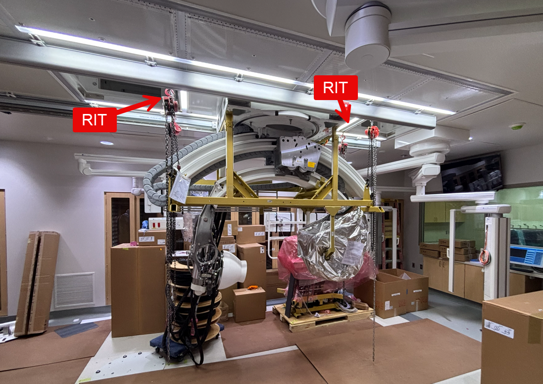
Figure 9: Side view of Siemens installing C-arm
Figure 10: End view of Siemens installing C-arm
Retention on Site
The RIT should be saved on site in the event the Siemens equipment requires future service or removal.
Contacting Support
You can reach SLD Technology Support by:
- Submitting a ticket online: Click: "Submit a Ticket" at the bottom of this article or at www.sldus.com/support
- Submit a ticket via Email: support@sldus.com
- Phone: +1 (503) 744-0002, Option 2
Figure 11: Submit a ticket online
Copyright © 2025 SLD Technology, Inc.
All rights reserved. AirFRAME®, LEDiffuser®, uLED®, AirFRAME-LT® and associated marks are trademarks of SLD Technology, Inc. Unauthorized reproduction, distribution, or use of this manual or any portion thereof is strictly prohibited and may violate applicable laws. SLD Technology reserves the right to make changes to products, specifications, or this manual without notice. The information herein is believed to be accurate at the time of publication; however, SLD assumes no responsibility for errors, omissions, or the consequences of use.
Related Articles
Installation Manual - AirFRAME®
NOTICE: General Reference Only The information provided in this article is for general reference purposes only and does not constitute project-specific guidance. SLD Technology products are engineered to order, and their installation must comply with ...Installation Contractor Training
AirFRAME® installation should only be completed by contractors who have been trained by SLD Technology, Inc. Since some installation characteristics can change with custom systems, a contractor training session should be booked for every installation ...Lens Logo Installation
NOTICE: General Reference Only The information provided in this Knowledge Base is for general reference purposes only and does not constitute project-specific guidance. SLD Technology products are engineered to order, and their installation must ...Anchorage & Lateral Bracing
All information contained in this Knowledge Base is provided for reference only. SLD products are engineered to order so the detailed requirements of any particular installation will be coordinated according to the codes, requirements, and ...Receiving and Storing SLD Products
NOTICE: General Reference Only The information provided in this Knowledge Base is for general reference purposes only and does not constitute project-specific guidance. SLD Technology products are engineered to order, and their installation must ...