Unistrut Embeds


NOTICE: General Reference Only
The information provided in this article is for general reference purposes only and does not constitute project-specific guidance. SLD Technology products are engineered to order, and their installation must comply with all applicable codes, standards, and project-specific specifications. In all cases, the approved project documentation and requirements take precedence over any general information contained herein. For project-specific instructions, contact your SLD Project Manager or the SLD Product Support Team at: support@sldus.com.
Introduction:
Operating Rooms with ceiling-mounted imaging equipment, MAVIG ceiling track systems, and other rail-supported ceiling systems mount that equipment to AirFRAME® using embedded Unistrut (P5500T deep-channel) sections manufactured by SLD. This applies whether the space is called a hybrid OR, cath lab, EP lab, interventional suite, or something else. These Unistrut sections are secured directly to the AirFRAME HSS tube steel frame, which serves as the structural support system.
When AirFRAME supports these systems, no additional field-installed or “stick-built” Unistrut supports are needed. SLD provides this scope where it is called out in SLD submittals or otherwise noted.
NOTE: Why SLD Unistrut Embeds Are Shorter
SLD Unistrut embeds are much shorter in length than the Unistrut used in stick-built or traditional ceiling support systems. The main reason is airflow.
- More airflow over the patient means a safer air delivery area.
- There are minimum required air delivery areas over the table.
- Unistrut that spans the full width of the room takes up ceiling space that would otherwise be used for air delivery.
By using Unistrut only where equipment needs support, SLD gets the most out of the air delivery area. This improves both airflow and patient safety.
Example Configurations
Bi-Plane Example:
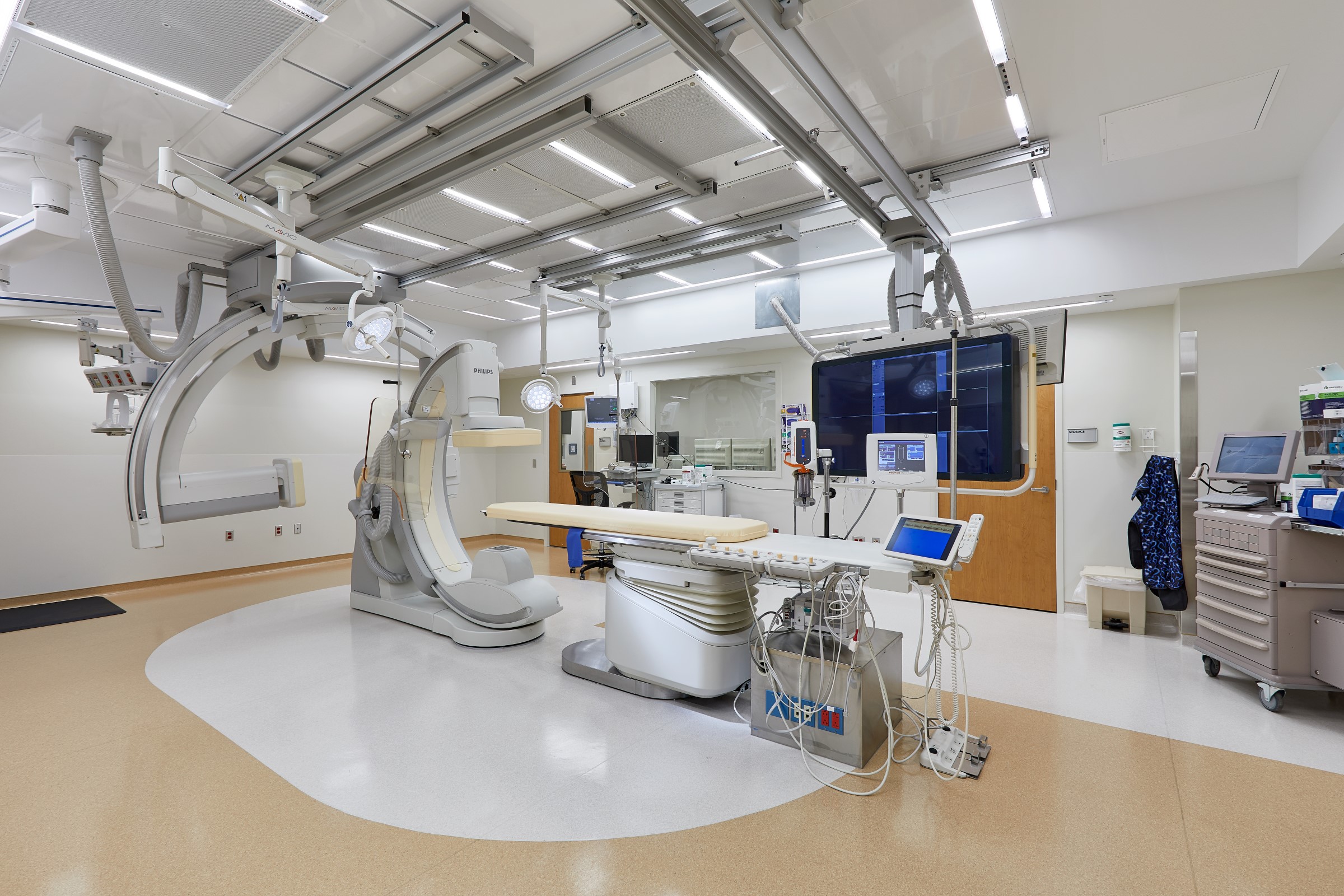
Below is an example of a Bi-Plane imaging room with one C-arm, one TV Monitor, and two MAVIG tracks that are all ceiling-hung supported by AirFRAME.
Single-Plane Example:
Below is an example of a single-plane room with boom-mounted shields and TVs:
Attachment Designs:
SLD has used two methods to attach Unistrut embeds to the AirFRAME structural tube. Leveling works the same way with both, but the attachment method determines how it is adjusted in the field.
Through-bot (current design):
The Unistrut embed is bolted through the AirFRAME tube, with a nut on the top side of the tube. SLD used this method originally, moved to riv nuts for a time, and then returned to through-bolts after HCAI (formerly OSHPD) would not accept riv nuts. SLD has since made through-bolts the standard on all projects nationwide.
Because the nut sits on top of the tube, someone has to hold it with a wrench from above any time an embed is removed or reinstalled. The top of the tube must be accessible for any adjustment.
Riv Nut (Previous Design):
The Unistrut embed is bolted into riv nuts installed in the AirFRAME tube. Some existing projects still use this design. All adjustments are made from below, so no access above the tube is needed.
ALERT: Set Elevation Before the Ceiling Closes (Through-Bolt)
All through-bolted Unistrut embeds must be at the correct elevation and level before any hard-lid ceiling is installed. Once the hard lid is in, the top nut can no longer be reached (unless sufficient access is provided), and adjustments may require opening the ceiling.
Field Leveling:
Construction tolerances add up across the SLD factory, the building structure, and other field conditions. To account for this, Unistrut embeds can be adjusted in the field with the provided shim plates. Some shims come pre-installed and others ship loose, so the embeds can be raised or lowered to stay within the equipment manufacturer’s tolerances.
Installing Contractor Responsibility:
- Install the AirFRAME plumb, level and at the correct height relative to the finished floor or top of the finished floor plate (reference imaging equipment manufacturer specifications).
- Verify that the Unistrut is level across all pieces and within imaging equipment manufacturer tolerances.
- For the through-bolt design, complete all Unistrut elevation and level verification before the hard-lid ceiling is installed.
- Tools recommended: magnetic-tip tape measure and laser level. For through-bolts, also bring a wrench for the top nut. For riv nuts, also bring a calibrated torque wrench.
ALERT: Lowest Strut Height Critical
Verify that the lowest Unistrut section meets the imaging equipment manufacturer’s specified height requirement, measured from the bottom of the strut to the top of the table base plate or finished floor (depending on imaging equipment manufacurer's specifications). Missing this requirement can lead to costly rework. Lowering Unistrut embeds is much easier than raising the entire AirFRAME assembly or grinding the floor to reach the proper height tolerance.
Unistrut Assembly:
Inverted assembly drawing:
Removed assembly with shims staged:
Room-side close-up view of installed assembly from below:
Assembly removed:
Adjustment:
Through-bold Design
No specific torque value is required for through-bolts. Tighten securely.
- Get access to the top of the tube above the assembly.
- Hold the top nut with a wrench while you loosen the bolts from below. Keep track of all factory-installed hardware.
- Remove the full assembly from the slot.
- Install or remove shims as needed.
- Reinstall the assembly with all factory hardware, including the lock washers and plate washers.
- Hold the top nut with a wrench and tighten the bolts securely.
Riv Nut Design

WARNING: Riv Nut Torque Requirement
Riv nut assembly bolts are factory-torqued to 23 ft-lbs (31.18 N·m) and marked for verification. Do not exceed this torque. Over-torquing can pull the riv nut out of the tube. Always reinstall with a calibrated torque wrench.
- Loosen the bolts retaining the Unistrut assembly. Keep track of all factory-installed hardware.
- Remove the full assembly from the slot.
- Install or remove shims as needed.
- Reinstall the assembly with all factory hardware, including the lock washers and plate washers.
- Using a calibrated torque wrench, tighten the bolts to 23 ft-lbs (31.18 N·m).
- Using calibrated torque wrench, tighten bolts to 23 ft-lbs (31.18 newton-meters)
Contacting Support
You can reach the SLD Support Team
by:
- Submitting a ticket online: Click: "Submit a Ticket" at the bottom of www.sldus.com/support
- Submit a ticket via Email: support@sldus.com
- Phone: +1 (503) 744-0002, Option 2
Related Articles
Installation Contractor Training
AirFRAME® installation should only be completed by contractors who have been trained by SLD Technology, Inc. Since some installation characteristics can change with custom systems, a contractor training session should be booked for every installation ...Installation Manual - AirFRAME®
NOTICE: General Reference Only The information provided in this article is for general reference purposes only and does not constitute project-specific guidance. SLD Technology products are engineered to order, and their installation must comply with ...Siemens Rail Installation
NOTICE: General Reference Only The information provided in this Knowledge Base is for general reference purposes only and does not constitute project-specific guidance. SLD Technology products are engineered to order, and their installation must ...Anchorage & Lateral Bracing
All information contained in this Knowledge Base is provided for reference only. SLD products are engineered to order so the detailed requirements of any particular installation will be coordinated according to the codes, requirements, and ...