Electrical Engineers/Contractors: Please contact our
Support Team to schedule a web-meeting walkthrough of VLD
prior to submitting your final plans/drawings. VLD is fundamentally different than standard LED lighting and
requires proper coordination.
What is Visible Light Decontamination (VLD)?
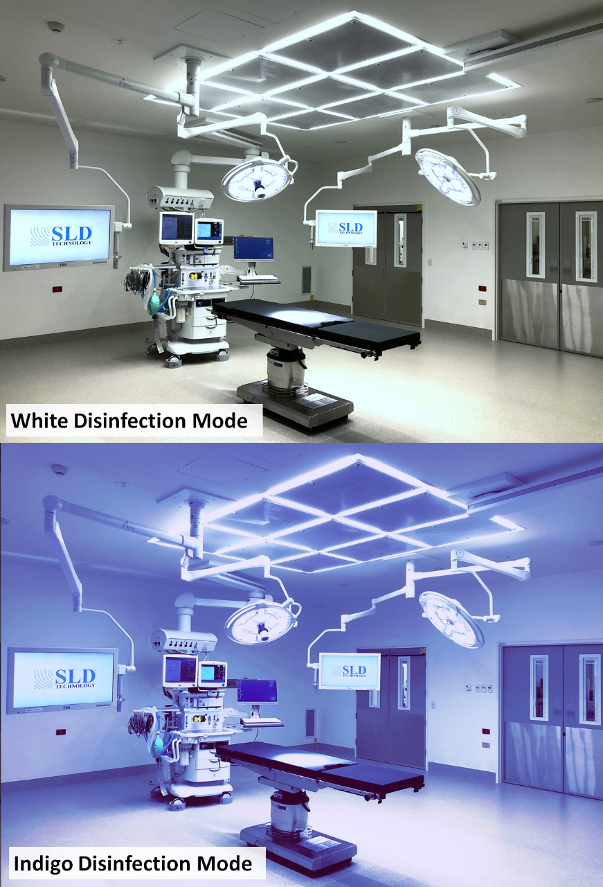
Visible Light Decontamination (VLD) is a continuous environmental decontamination system that uses safe visible light to decontaminate. Unlike UV lights, VLD operates in the visible light spectrum at 405nm which is not harmful to patients or surfaces. The system uses two modes of decontamination, automatically switching between modes depending on room occupancy.
White Decontamination Mode
(Occupied):
When the room becomes occupied, the system automatically switches to a reduced dose of 30% VLD light mixed with white light to provide ambient room lighting as well as continuous environmental decontamination.
VLD Decontamination Mode
(Unoccupied):
When the room is unoccupied for a customer-defined period of time up to 30-minutes, the system automatically switches to a full dose 100% of VLD light to provide maximum continuous decontamination. Regardless of the state users left the room, all fixtures will change to VLD Mode making the room appear purple/blue.
Installation with AirFRAME®
A typical AirFRAME with VLD installation will consist of the following components: VLD fixtures (quantity of AirFRAME lighting plus hard-lid lighting is dependent on volume of space in room, ie: dosing), one VLD controller, three Passive Infrared (PIR) sensors, one Ultrasonic (US) sensor, an optional Override Switch (by others), and 0-10v dimming controls (by others). For smaller room applications such as patient rooms and restrooms, a single VLD sensor can replace the need for other sensors and dimmers.
VLD Fixtures:
The AirFRAME lighting array consists of integrated VLD fixtures.
AirFRAME lighting is often supplemented by VLD troffers and/or can lights in order to achieve both lighting levels and proper VLD decontamination dosing.
The AirFRAME integrated lighting as well as perimeter hard-lid lighting all operate as a single complete VLD decontamination system.
VLD Controller:
The VLD controller’s function is to switch between White Decontamination Mode (Occupied) and VLD Decontamination Mode (Unoccupied) via sensor input data.
All ceiling sensors as well as optional override switch are wired to Bays 1-5 on the controller input terminals.
A Building Management System (BMS) can monitor the room occupancy via Interconnect terminals (IC1 / IC2) on the controller.
A control line from the Brown/Yellow terminals on the controller is wired to each fixture and/or driver enclosure.
There are sensor status lights; however, there are no user inputs on the VLD controller.
Green indicates the sensor associated with that bay is connected.
Red indicated the sensor associated with that bay is triggering occupancy.
In the event the VLD100 controller loses power, the system defaults to White Decontamination Mode.
Ceiling Sensors:
There are three Passive Infrared (PIR) and one Ultrasonic (US) sensor included with each VLD controls kit.
Each sensor has 3 low voltage wires (red(+), black(-), and blue(occ)) that require a home run back to the VLD controller. When the sensor detects occupancy, it sends a signal to the VLD controller for the duration the sensor is programmed for. If no occupancy is detected by the sensor for the duration of the sensor-programmed length of time, the sensor stops sending its signal to the controller. If no other sensors are sending occupied signals, the VLD controller will send the signal to the lights to change to VLD Decontamination Mode. If any sensor detects occupancy, the controller will switch to White Decontamination Mode.
The sensors are what determine the time delay between occupied mode and unoccupied mode. Each sensor is adjustable from 30-seconds to 30-minutes. Sensors are factory set to 30-minutes.
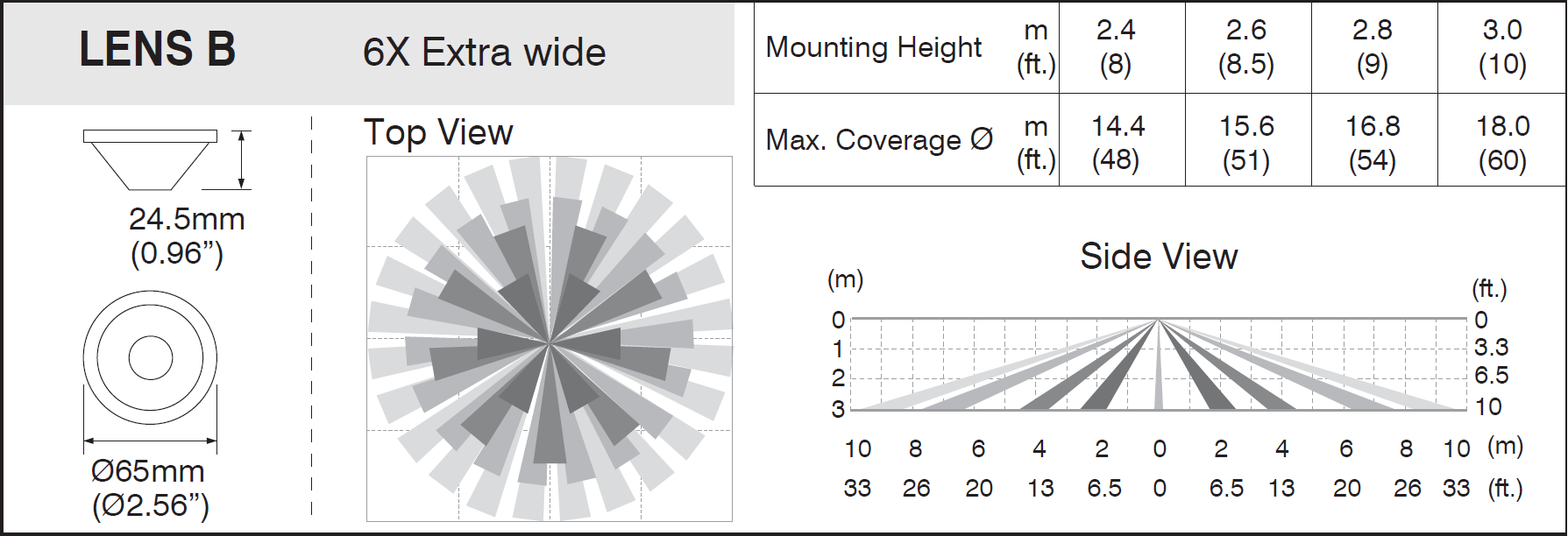
PIR Sensor Coverage:
PIR Sensor Installation:
Be sure to remove screw nut before threading sensor onto the base then use screw nut to secure sensor to base. Failure to do so will result in the sensor sticking down into the room:
Only the Red(+), Black(-) and Blue(occ) wires need to be pulled to the VLD controller and connected. Other wires if present (yellow and orange) can be capped at the back of the sensor.
Connect each PIR sensor to Bays 1, 2, and 3 respectively on the VLD controller.
Each sensor needs its own home run back to the VLD controller. Do NOT daisy-chain sensors.
Only Red(+), Black(-) and Blue(occ) wires need to be pulled to the VLD controller and connected. The "Manual Switch" terminal is unused.
Connect the US sensor to Bay 4 on the VLD controller.
Each sensor needs its own home run back to the VLD controller. Do NOT daisy-chain sensors.
Override Switch (optional, by others):
This optional override switch holds the room in White Decontamination Mode for as long as the switch is engaged. It is often requested as peace-of-mind that there is a manual backup in the case (though rare) of sensor and/or controller failure.
If utilized, care should be taken in the design and labeling of the switch in order to avoid accidental engagement.
It is recommended that this switch be located at a high elevation on the wall similar to where an emergency lighting test button may be located, using a keyed toggle switch, switch covers similar to fire alarm pull station, explicit labeling, etc. to ensure users in the room do not accidentally engage the override.
The switch can be a simple single-pole light switch or any other type of low voltage switch that OPENS the low voltage control circuit on the YELLOW wire between the VLD controller and any VLD fixture. It is best practice for this pair of wires to be pulled to the VLD controller rather than a j-box downstream.
If a user mistakenly engages the override switch or it is forgotten about after a case, the lights will never switch into VLD Decontamination Mode.
LABEL RECOMMENDATION:
Header: "VLD OVERRIDE SWITCH"
Switch ON position: "NORMAL"
Switch OFF position: "OVERRIDE"
Footer: "OVERRIDE FOR EMERGENCY ONLY"
Dimming Controls (White Mode 0-10v dim-to-off):
Selecting an appropriate dimmer is imperative to proper user control of the white lighting mode. VLD lights require 24/7 line voltage (120~277VAC) for VLD modes to function properly. General users of the room should never have the ability to cut line voltage (120~277V) to the lighting fixtures. The lights in white mode can be turned off via dim-to-off on the 0-10v control line (Purple & Gray or Pink wires). When the dimming controls send <13V on the dimming circuit, the white lights will turn off.
For example, if a simple slide switch (LED 0-10V capable) is installed, sliding the slider all the way down (<1.3v) will turn the lights off. All the way up (10v) is full brightness and everything in between is dimming 100% down to 1% then to off. Care should be taken when selecting lighting controls compatible with dim-to-off and LED 0-10v controls. Control systems should NOT cut power to the lights to turn them off.
Most LED 0-10V dimmers include a line voltage switch leg. This wire can either be capped or connected to a relay (provided by others) that closes the 0-10V control line. Closing/shorting the 0-10v controll line will turn the lights off in white mode.
For simple on/off control, use a toggle switch to close the 0-10v dim-to-off circuit.
Example wiring using Leviton Decora IP710 series dimmer with VLD:
A general user of the room should NEVER have the ability to cut AC line voltage (120~277V) to the lighting fixtures. They require 24/7 line voltage for the VLD modes to function properly. White light controls are SOLEY via low voltage (0-10V Dim-to-Off) controls.
White lighting can be connected to override technology such as Imaging equipment foot pedals by connecting relay terminals between the dimmer and VLD fixture.
By closing (shorting) the 0-10v line, the lights will turn off in white mode. When the relay opens, the lights will revert back to the previously selected dim level.
Do NOT wire foot pedal to disconnect AC line voltage (120~277V). Lights will flash to full brightness before reverting back to previously selected dim level causing staff discomfort and improper VLD functions reducing efficacy.
A general user of the room should NEVER have the ability to cut AC line voltage (120~277V) to the lighting fixtures. They require 24/7 line voltage for the VLD modes to function properly. White light controls are SOLEY via low voltage (0-10V Dim-to-Off) controls.
Interconnect (BMS occupancy status monitoring):
The VLD controller is equipped with interconnect terminals labeled IC1 and IC2 for connection to a BMS. The VLD controller will output the below voltages on these terminals depending on the state of occupancy:
0 volts = Unoccupied
5 volts = Occupied
Monitoring systems capable of detecting voltage outputs can be connected to these terminals.
Wiring:
A general user of the room should NEVER have the ability to cut AC line voltage (120~277V) to the lighting fixtures. They require 24/7 line voltage for the VLD modes to function properly. White light controls are SOLEY via low voltage (0-10V Dim-to-Off) controls.
Never run low voltage control wiring (0-10VDC) in the same conduit as line voltage (120~277VAC).
Each VLD fixture and AirFRAME electrical enclosure has 7 connection wires or terminal block points which can be daisy-chained to each fixture/enclosure.
(3) are for 120/277V house power connection (Line, Neutral, & Ground)
(2) are for 0-10V dimming which connect to building controls and/or room switches (dim-to-off)
(2) run back to the VLD controller to control the VLD modes
AirFRAME Electrical Enclosures:
Room Example:
The Orange lines are dimming control (0-10v) from three dimmers that control White Mode lights for perimeter down-lights, AirFRAME perimeter, and AirFRAME interior lights.
The Purple lines are the VLD 0-10v control lines that tell the lights when to switch into VLD mode.
The Green lines are the sensor control lines that take sensor inputs to tell the VLD controller to stay in white mode.
Not shown are the 120/277V power lines that will need to go to each fixture j-box and VLD Controller. These should be switched providing 24/7 power.
Smaller Room Applications:
For smaller room applications such as patient room, smaller restrooms, waiting areas, etc., a single VLD75 controller can take the place of additional sensors and dimming controls.
VLD75 Controller:
The VLD75 controller is a sensor/controller combo unit available in either a ceiling mounted or a wall mounted version. The intent of this unit is to control dual-mode VLD lights in smaller spaces where multiple sensors are not needed.
A single VLD75 controller controls all VLD lights within a single room taking the place of the VLD100 controller and all separate ceiling sensors.
Dimming controls as discussed above can be used but are not a requirement.
RCP Drawing Terminology:
VLD - Visible Light Decontamination
Squares, rectangles, and/or circles labeled as 'VLD' on SLD drawings reference required hard-lid lighting based on VLD dosing requirements. Although hard-lid lighting may be required, indicated fixtures may be interchangeable based on room dosing. See dosing equivalents below.
PIR - Passive Infrared Sensor
Ceiling mounted sensor meant to sense movement in range. Similar to home alarm system motion sensors, PIR sensors are based on Passive Infrared technology which detects explicit movements.
US - Ultrasonic Sensor
Ceiling mounted sensor meant to sense small, finite movements ultrasonically. This sensor is meant to detect occupancy in cases where movement in the room is minimal. Ideally this sensor is placed as close as ceiling space allows to the surgical area. This sensor is ultrasonic and may need to be adjusted after air balance.
Dosing Equivalents:
SLD drawings will show the minimum required lighting to achieve proper VLD dosing. More lighting can be added upon request; however, lighting cannot be removed below minimum dosing requirements. The size of the lighting fixtures can be adjusted based on the following criteria:
One 1'x4' Troffer = One 2'x2' Troffer = Two Ø6" Cans
One 2'x4' Troffer = Two 2'x2' Troffers = Two 1'x4' Troffers = Four Ø6" Cans